


 English
 中文简体
中文简体 Español
 русский
 عربى
عربى
Content
- 1 How Does Injection Molding Work? The Direct Answer
- 2 The Injection Molding Cycle, Step by Step
- 3 Inside the Machine: The Core Components That Make It Work
- 4 Injection Molding Materials: What Actually Goes Into the Mold
- 5 Process Parameters That Determine Final Part Quality
- 6 Common Defects and What Actually Causes Them
- 7 Part Design Choices That Affect How the Process Behaves
- 8 Tooling Considerations Before Production Begins
- 9 Quality Control Throughout Production
- 10 Automation, Sustainability, and Where the Process Is Headed
- 11 Where Injection Molding Is Used Today
- 12 Frequently Asked Questions
- 12.1 How long does one injection molding cycle take?
- 12.2 What is the difference between thermoplastics and thermosets in injection molding?
- 12.3 Which injection molding materials are easiest to process?
- 12.4 Why does wall thickness matter so much?
- 12.5 Can injection molding produce transparent parts?
- 12.6 What causes flash at the parting line?
- 12.7 What is the difference between a hot runner and a cold runner mold?
- 12.8 How many cavities should a production mold have?
- 12.9 Can regrind or recycled material be used without hurting part quality?
How Does Injection Molding Work? The Direct Answer
Injection molding works by melting solid plastic pellets into a liquid state, forcing that melt under high pressure into a closed steel mold cavity, holding the pressure while the part cools and solidifies, then opening the mold and ejecting the finished part. A full cycle repeats this sequence automatically, often in under a minute, which is why the process is the backbone of high-volume plastic part production worldwide.
The whole operation runs on four connected stages: clamping, injection, cooling, and ejection. Each stage is controlled by machine parameters such as barrel temperature, injection speed, holding pressure, and cooling time, and the correct combination of these settings depends heavily on which injection molding materials are being processed. A technical part made from polycarbonate behaves very differently under heat and pressure than a flexible cap made from polypropylene, so understanding the mechanics of the process and the behavior of the material go hand in hand.
What makes injection molding attractive at scale is repeatability. Once a mold is cut and the process window is validated, the same part can come out within tight dimensional tolerances thousands or millions of times in a row, with very little variation from shot to shot. That consistency is what separates it from processes like 3D printing or CNC machining, which are excellent for prototypes and low volumes but do not scale economically once production quantities move into the tens of thousands.
The sections below break the process down phase by phase, explain what happens inside the machine, compare the most common resins used in production, walk through the parameters and design choices that separate a clean part from a defective one, and cover the practical questions that come up once a project moves from concept toward an actual production run.
The Injection Molding Cycle, Step by Step
A single molding cycle is the time between one mold closing and the next mold closing. Depending on part size, wall thickness, and material, a cycle can run anywhere from about 10 seconds for a thin-wall packaging item to well over 120 seconds for a thick technical component, based on benchmarking data published across the molding industry in 2025 and 2026. Each cycle moves through five distinct phases, and understanding what happens in each one makes it much easier to diagnose problems later.
1. Clamping
The two halves of the mold are closed and locked together by the clamping unit. The clamping force must be high enough to keep the mold shut against the pressure of the incoming molten plastic; undersized clamp tonnage is one of the most common causes of flash at the parting line. Clamp force is generally estimated by multiplying the projected area of the part and runner system by a cavity pressure factor, which typically falls somewhere between 2 and 8 tons per square inch depending on the material and wall thickness involved.
2. Injection (Fill)
A rotating screw pushes molten resin through the nozzle, through the sprue, runners, and gates, and into the cavity. Fill time is usually very short, typically 0.5 to 5 seconds, since most of the cavity volume needs to be filled before the melt front begins to cool and freeze. Modern machines use multi-stage velocity profiles during fill, starting slow to avoid jetting near the gate, accelerating through the body of the part, and slowing again as the melt front approaches the last areas to fill, which reduces air entrapment and visible flow marks.
3. Packing and Holding
Once the cavity is nominally full, the machine switches to a lower holding pressure to pack additional material into the mold as the part begins to shrink. This stage typically lasts 1 to 15 seconds depending on wall thickness, and it is the primary control point for preventing sink marks and voids. Packing continues until the gate freezes off; once the gate solidifies, no more material can enter the cavity, so any packing pressure applied after that point has no further effect on the part.
4. Cooling
This is usually the longest portion of the cycle. The part must cool below its ejection temperature throughout its thickest cross-section before the mold can safely open. Cooling time is driven mainly by wall thickness and the material's thermal diffusivity, and it commonly accounts for well over half of total cycle time on thicker parts. Screw recovery, which plasticizes the resin for the next shot, typically overlaps with cooling rather than adding extra time to the cycle, so the longer of the two durations is what actually governs total cycle length.
5. Mold Opening and Ejection
The mold opens, ejector pins push the solidified part free, and the cycle resets. Ejection itself is fast, generally 0.5 to 2 seconds, though parts with undercuts, threaded inserts, or side-action slides can add several seconds here. On automated lines, a robot arm often removes the part directly from the mold during this window to keep the cell running without an operator standing at the press.
| Cycle Phase | Typical Duration | Main Driver |
|---|---|---|
| Injection (fill) | 0.5 - 5 seconds | Shot volume, injection rate |
| Packing and holding | 1 - 15 seconds | Wall thickness, gate freeze time |
| Cooling | 10 - 60+ seconds | Wall thickness, thermal diffusivity |
| Mold open, ejection, close | 3 - 8 seconds | Machine speed, part geometry |
Cycle time is not just a technical curiosity; it is directly tied to cost. Because a molding machine represents a large fixed hourly cost, every second added to a cycle spreads that cost across fewer parts. On a 4-cavity mold running a 30-second cycle, output works out to roughly 480 parts per hour; shaving the cycle down to 25 seconds lifts that to around 576 parts per hour, a meaningful production gain without any additional capital investment. This is why experienced process engineers treat cycle time reduction as an ongoing optimization exercise rather than a one-time setup task.
Inside the Machine: The Core Components That Make It Work
An injection molding machine is built around two functional halves that work together on every cycle: the injection unit that prepares and delivers the melt, and the clamping unit that holds the mold and manages part removal.
The Injection Unit
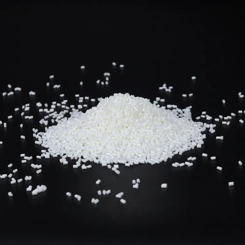
- Hopper - feeds dry resin pellets into the barrel, usually after a pre-drying stage for moisture-sensitive materials such as nylon or polycarbonate.
- Heated barrel - surrounds the screw and raises the resin above its melting or softening point through a combination of external heater bands and shear heat generated by the rotating screw itself.
- Reciprocating screw - rotates to plasticize and convey the melt forward, then acts as a piston to inject it into the mold. The screw is divided into three functional zones: a feed zone that moves solid pellets forward, a compression zone that gradually melts and compresses the material, and a metering zone that homogenizes the melt before it reaches the nozzle.
- Nozzle - the transition point where melt leaves the barrel and enters the mold's sprue bushing. Nozzle tip design and temperature are tuned to prevent drooling between shots while still allowing free flow during injection.
Screw Design and L/D Ratio
Screw length is usually expressed as a length-to-diameter, or L/D, ratio. General-purpose screws commonly fall in the 18:1 to 24:1 range, giving enough length for thorough melting and mixing without excessive residence time that could degrade heat-sensitive resins. Screws intended for glass-filled or heavily colored materials often use a different compression ratio to protect the reinforcing fibers or pigment particles from excessive shear.
The Clamping Unit
- Fixed and moving platens - hold the two mold halves in alignment and distribute clamping force evenly across the mold face.
- Tie bars and toggle or hydraulic clamp mechanism - generate and maintain clamping force, commonly rated in tons, matched to the projected area of the part. Toggle clamps are fast and mechanically efficient for smaller machines, while hydraulic and hybrid clamps are often preferred on larger tonnage presses where precise, adjustable force control matters more.
- Ejector system - pins, sleeves, stripper plates, or air blasts that release the finished part from the core side of the mold without distorting it while it is still warm.
The Mold Itself
The mold contains the cavity and core that shape the part, a runner system that channels melt to one or more gates, and internal cooling channels that regulate mold surface temperature. Mold temperature control is just as important as barrel temperature; a mold that runs too cold can cause poor surface finish and short shots, while one that runs too hot extends cooling time unnecessarily and can promote warping in semi-crystalline resins.
Cold Runner vs Hot Runner Systems
Cold runner molds solidify the feed channels along with the part, and that runner is either scrapped, reground, or trimmed off after each cycle. Hot runner molds instead keep the runner channels heated and molten between shots, feeding melt directly into the cavity without producing runner waste. Hot runners cost more to build and maintain but reduce material waste, shorten cycle time by removing the runner-cooling step, and are the standard choice on high-cavitation tools running large production volumes.
Injection Molding Materials: What Actually Goes Into the Mold
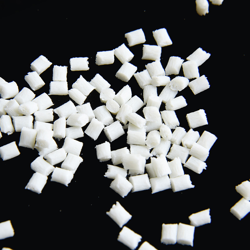
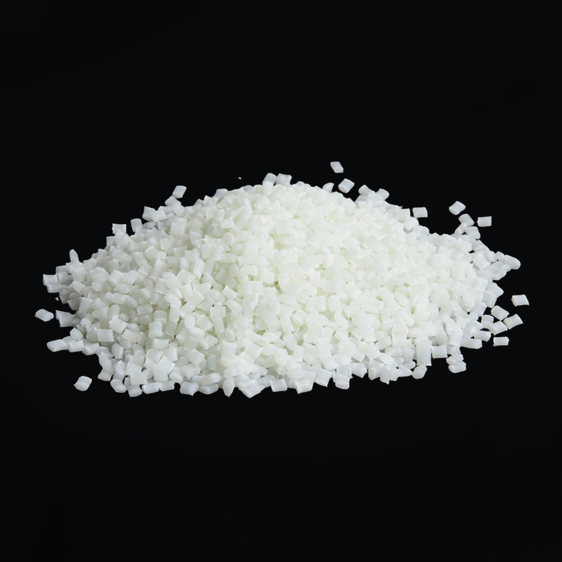
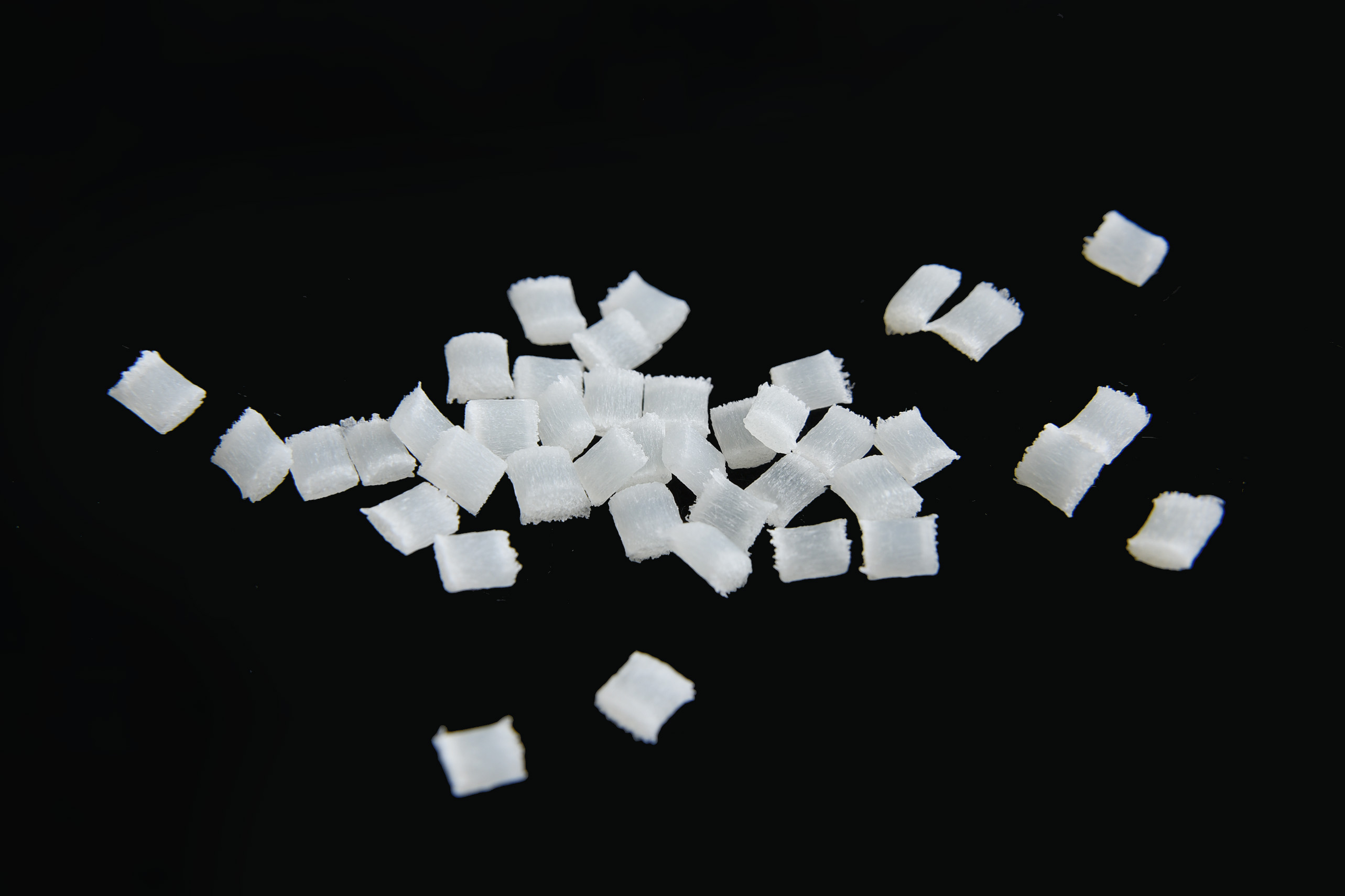
The process itself is only half the story. The choice of injection molding materials determines melt temperature, shrinkage rate, cycle time, and final part performance. Most production work falls into three broad material families, and picking the wrong one for a given application is one of the most expensive mistakes a project can make, since it often means recutting steel after tooling is already finished.
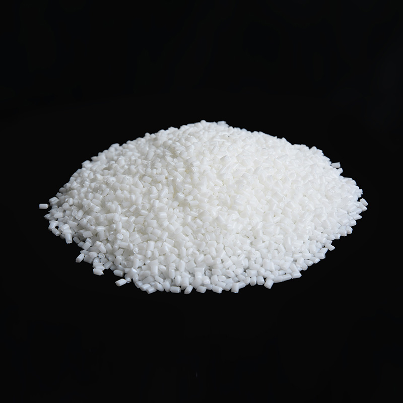
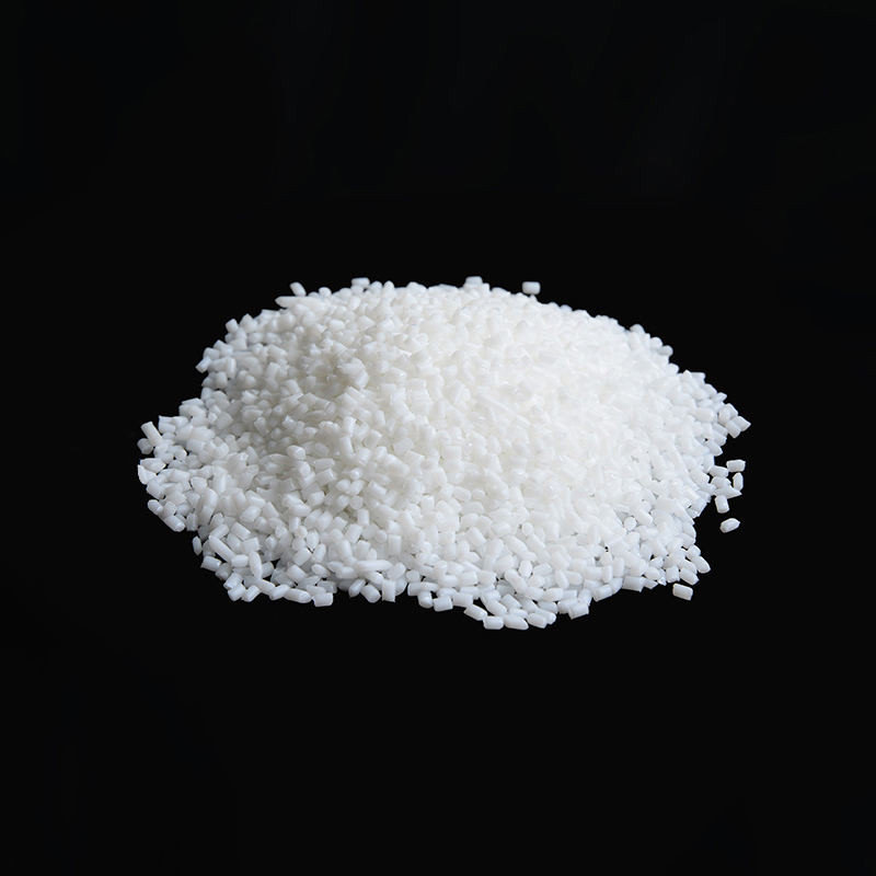
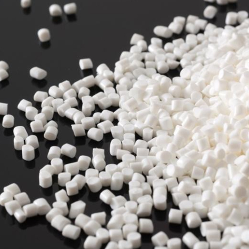
Thermoplastics (the vast majority of parts)
Thermoplastics soften when heated and solidify when cooled, and this cycle can be repeated, which is why regrind and sprue scrap can often be reprocessed. Common examples include polypropylene, ABS, polyethylene, polycarbonate, nylon, POM, and PMMA. Within thermoplastics there is a further split between amorphous resins, which soften gradually over a temperature range, and semi-crystalline resins, which melt sharply at a defined point and typically shrink more during cooling.
Thermosets
Thermosets undergo a chemical cross-linking reaction during molding and cannot be remelted afterward. They are used where high heat resistance and dimensional stability under sustained load are required, such as certain electrical components and heat-exposed housings.
Thermoplastic Elastomers
TPE and TPU combine rubber-like flexibility with the processing convenience of a thermoplastic, and are frequently overmolded onto a rigid substrate to create soft-touch grips and seals. Overmolding requires careful attention to bond strength between the soft material and the rigid base resin, since not every material pair adheres well without a compatible interface layer.
| Material | Typical Melt Temp | Key Characteristics | Common Uses |
|---|---|---|---|
| Polypropylene (PP) | 200 - 280 C | Low cost, chemical resistant, living-hinge friendly | Caps, containers, hinged lids |
| ABS | 220 - 260 C | Good impact strength, easy to finish and plate | Housings, enclosures, appliance parts |
| Polycarbonate (PC) | 280 - 320 C | High impact strength, transparency, heat resistance | Lenses, protective covers, technical parts |
| Nylon (PA6 / PA66) | 240 - 290 C | High strength, wear resistance, absorbs moisture | Gears, structural clips, brackets |
| POM (Acetal) | 190 - 230 C | Low friction, high stiffness, dimensional stability | Gears, sliding mechanisms, connectors |
| Polyethylene (HDPE/LDPE) | 180 - 260 C | Flexible, moisture resistant, low cost | Bottles, caps, flexible fittings |
| PMMA (Acrylic) | 210 - 250 C | High optical clarity, scratch resistance | Light guides, display covers, lenses |
| TPE / TPU | 180 - 230 C | Soft-touch flexibility, abrasion resistance | Grips, seals, overmolded components |
Material selection also affects shrinkage, which mold designers compensate for when cutting cavity dimensions. Semi-crystalline resins such as PP, nylon, and POM tend to shrink more and less predictably than amorphous resins such as ABS and polycarbonate, which is why shrinkage tables for each specific grade are checked before tooling is finalized. Reinforced grades add another variable: glass fiber loading typically reduces overall shrinkage but can introduce directional, or anisotropic, shrinkage along the direction of fiber orientation, which needs to be accounted for in the mold design rather than corrected afterward.
Additives and Modified Grades
Base resins are frequently modified to hit a specific performance target. Glass fiber reinforcement raises stiffness and heat deflection temperature. Flame retardant packages are added for electrical enclosures. UV stabilizers extend outdoor service life for parts exposed to sunlight. Impact modifiers improve low-temperature toughness. Each additive package can shift the melt temperature window, shrinkage behavior, and flow characteristics slightly, so a material data sheet for the specific grade being used, not just the generic resin family, should guide the actual process settings.
Process Parameters That Determine Final Part Quality
Four settings interact to decide whether a part comes out dimensionally accurate and cosmetically clean.
- Melt temperature - set based on the resin's processing window; too low causes poor flow and weld lines, too high risks material degradation and discoloration.
- Injection speed and pressure - controls how fast the cavity fills; faster fill reduces the chance of premature freezing in thin sections but can trap air or cause jetting near the gate if set too aggressively.
- Holding pressure and time - compensates for volumetric shrinkage as the part cools; ends once the gate freezes off, after which additional holding time has no further effect.
- Mold temperature - influences surface finish, crystallinity in semi-crystalline resins, and overall cooling time.
Cycle time optimization work published in 2026 industry guides shows that most molders run 20 to 40 percent slower than their theoretical optimum because of avoidable design or process inefficiencies, and that even a 10-second reduction on a 60-second cycle can add tens of thousands of dollars in annual profit per machine on high-volume programs, while a 2-second increase can cost a comparable amount in lost output over a year. This is one of the reasons molders spend significant engineering time tuning these four parameters rather than treating them as fixed settings.
A Simple Cooling Time Example
Cooling time is commonly estimated using the square of wall thickness, which is why doubling wall thickness does not simply double cooling time, it roughly quadruples it. A part with a 2 mm nominal wall might cool in around 8 to 12 seconds, while a similar part in the same material with a 4 mm wall can require 30 seconds or more to reach a safe ejection temperature. This relationship is one of the strongest arguments for keeping wall sections thin and consistent wherever the part's structural requirements allow it.
Scientific Molding and Process Windows
Rather than tuning parameters by trial and error on every job, many molders establish a documented process window through a structured study, often called scientific molding or design of experiments. This approach maps how variations in injection speed, pack pressure, and cooling time affect part weight, dimensions, and appearance, then locks in a center-point process that leaves margin on both sides before defects appear. Parts produced this way tend to show far less shot-to-shot variation over a long production run.
Common Defects and What Actually Causes Them
Most molding defects trace back to an imbalance between fill speed, pressure, cooling, and material behavior rather than a single isolated mistake. Diagnosing a defect usually means working backward from the symptom to the most likely combination of causes.
| Defect | Typical Cause | Common Fix |
|---|---|---|
| Short shots | Insufficient pressure, undersized gate, premature freezing | Raise injection pressure or speed, enlarge gate |
| Sink marks | Inadequate packing relative to wall thickness | Increase pack pressure or time, reduce local thickness |
| Warping | Uneven cooling, inconsistent wall thickness | Balance mold cooling channels, adjust wall uniformity |
| Flash | Low clamp tonnage, worn mold surfaces | Increase clamp force, service parting line |
| Weld lines | Melt fronts meeting after flowing around a feature | Raise melt temperature, relocate gate |
| Burn marks | Trapped air igniting under compression | Add or clean venting at the affected area |
| Flow lines | Melt cooling unevenly as it advances | Raise mold or melt temperature, adjust fill speed |
| Brittleness or splay | Moisture in the resin or material degradation | Pre-dry material per spec, reduce residence time |
Part Design Choices That Affect How the Process Behaves
Because so much of cycle time and quality is decided before the mold is ever cut, part design has an outsized effect on how smoothly the process runs. Engineering teams often refer to this discipline as design for manufacturability, and applying it early consistently saves far more time than fixing problems after steel has already been cut.
Wall Thickness
Uniform wall thickness allows the melt to cool at a consistent rate, which reduces warping and sink marks. Thick, uneven sections are the single biggest driver of extended cooling time. Most general-purpose plastic parts fall somewhere between 1 mm and 4 mm in nominal wall thickness, with thinner sections used for packaging and thicker sections reserved for structural components.
Draft Angles
Vertical walls need a slight taper, generally starting around 1 to 2 degrees, so the part releases cleanly from the core without dragging or scuffing. Textured surfaces typically need additional draft beyond this baseline, since texture depth increases the mechanical grip between the part and the mold surface.
Ribs and Bosses
Ribs add stiffness without adding bulk, but a rib thicker than roughly 60 percent of the adjoining wall will often telegraph as a visible sink mark on the opposite surface. Bosses used for screw fastening should similarly be designed with a core-out or a thinner wall section to avoid the same telegraphing issue.
Gate Location and Type
Gate placement controls fill pattern, weld line location, and cosmetic gate marks. Edge gates, sub gates, and hot-tip gates each suit different part geometries and appearance requirements. Gates are usually positioned at the thickest section of the part so that packing pressure can reach the areas most prone to sinking before the gate freezes.
Undercuts and Side Actions
Features that would otherwise trap the part in the mold, such as snap clips or side holes, require sliders, lifters, or collapsible cores to release properly. These mechanisms add tooling cost and complexity, so designers weigh whether an undercut is truly necessary or whether the same function can be achieved with a straight-pull geometry.
Tooling Considerations Before Production Begins
Before any part reaches full production, the mold itself has to be designed, cut, and validated, and this step shapes both the timeline and the economics of the whole project.
Prototype, Bridge, and Production Tooling
Prototype tooling, often cut from aluminum, can deliver first parts in a matter of weeks and is useful for validating fit and function before committing to full production steel. Bridge tooling sits in between, offering more durability than a prototype tool while still being faster to build than a hardened production mold. Full production steel tooling takes longer to manufacture but is designed to run for hundreds of thousands or millions of cycles without significant wear.
Cavitation
A mold can be built with a single cavity or many cavities producing identical parts on every cycle. Higher cavitation increases tooling cost and complexity but multiplies output per cycle, which lowers the per-part cost on high-volume programs. Balancing runner length and cooling across every cavity becomes more difficult as cavity count rises, and an unbalanced multi-cavity mold can fill unevenly, producing good parts in some cavities and short shots in others.
Mold Steel and Expected Lifespan
Mold steel selection depends on expected production volume and the abrasiveness of the material being run. Softer tool steels are less expensive and adequate for shorter production runs, while hardened and sometimes surface-treated steels are used for long-life production tools or for abrasive glass-filled resins that would otherwise wear a softer cavity surface prematurely.
Quality Control Throughout Production
Consistency does not happen automatically just because a process runs on a machine. Ongoing quality control keeps a production run within specification from the first shot to the last.
- First article inspection - the initial parts from a new or repaired mold are measured against the drawing before the run is approved to continue.
- In-process shot weight monitoring - tracking part weight from shot to shot flags process drift, such as a developing short shot or a worn check ring, before parts fail visually.
- Dimensional sampling - periodic measurement against critical-to-function dimensions confirms the process remains centered within tolerance over a long run.
- Visual and cosmetic checks - operators or vision systems screen for flash, discoloration, and surface defects on parts destined for visible applications.
Automation, Sustainability, and Where the Process Is Headed
Injection molding is a mature process, but the way factories run it continues to evolve. Two trends stand out in recent industry reporting.
Digital Process Monitoring
Digital twin and process-monitoring platforms that mirror a real production cell in software are increasingly used to catch drift before it produces scrap, with case studies from major consulting firms reporting substantial return on investment when this technology is applied to established production lines. These systems compare live sensor data against the validated process window in real time and flag deviations before an operator would notice a visible defect.
Recycled and Regrind Content
Runner scrap from cold-runner molds is commonly reground and blended back into virgin resin at a controlled ratio, which reduces material cost and waste without significantly affecting part performance when the blend ratio stays within the resin supplier's guidance. Post-consumer recycled content is also being specified more frequently for non-critical components, though it typically requires additional process tuning since recycled feedstock can vary more in melt flow and moisture content than virgin material.
Energy Efficiency
All-electric and hybrid machines have continued to displace older full-hydraulic presses in many factories, since electric drives reduce idle energy consumption and offer more precise, repeatable control over injection velocity, which in turn tightens part-to-part consistency.
Where Injection Molding Is Used Today
The process scales efficiently from a few hundred parts to millions of units, which is why it dominates across a wide range of industries.
- Packaging - closures, caps, and thin-wall containers produced on short cycle times, often on high-cavitation hot-runner tools.
- Automotive - interior trim, connectors, and under-hood components molded from engineering resins that must tolerate heat and vibration.
- Consumer electronics - housings, buttons, and internal structural parts, frequently combining a rigid shell with an overmolded soft-touch grip.
- Industrial equipment - gears, brackets, and enclosures where dimensional consistency matters at high volume.
- Outdoor and leisure products - fittings, housings, and hardware that need UV resistance and weatherability alongside dimensional stability.
- Consumer goods - toys, household items, and everyday products that need to be produced repeatably at scale and at low unit cost.
Frequently Asked Questions
How long does one injection molding cycle take?
Most cycles fall between 10 and 60 seconds, though thin-wall packaging parts can cycle in under 10 seconds while thick technical components can take 120 seconds or more.
What is the difference between thermoplastics and thermosets in injection molding?
Thermoplastics can be reheated and reshaped repeatedly, which makes regrind possible. Thermosets chemically cross-link during molding and become permanently rigid, so they cannot be remelted once cured.
Which injection molding materials are easiest to process?
Polypropylene and ABS are generally considered forgiving materials because of their wide processing windows and predictable flow, which is one reason they are so common in everyday consumer parts.
Why does wall thickness matter so much?
Wall thickness controls cooling time, which is usually the longest phase of the cycle, and uneven thickness is the leading cause of warping and sink marks. Because cooling time scales roughly with the square of thickness, small increases in wall section can have an outsized effect on cycle time.
Can injection molding produce transparent parts?
Yes. Amorphous resins such as polycarbonate and PMMA are commonly molded into clear lenses, covers, and optical components, provided the mold surface is polished to an optical finish and the process is tuned to avoid trapped air or flow lines.
What causes flash at the parting line?
Flash usually points to insufficient clamping force relative to the injection pressure, a worn or damaged mold parting surface, or excessive injection speed pushing melt past the mold's seal.
What is the difference between a hot runner and a cold runner mold?
A cold runner solidifies along with the part and produces waste that must be trimmed or reground, while a hot runner keeps the feed channels molten between shots, reducing material waste and often shortening cycle time at the cost of a more complex and expensive mold.
How many cavities should a production mold have?
Cavity count depends on required volume, budget, and machine size. More cavities lower the per-part cost at high volumes but raise tooling cost and make it harder to keep every cavity filling evenly, so the right number is usually chosen through a cost-per-part analysis rather than a fixed rule.
Can regrind or recycled material be used without hurting part quality?
In most cases yes, provided the regrind ratio stays within the resin supplier's guidance and the material is properly dried before reprocessing. Higher regrind ratios or repeated reprocessing can gradually reduce mechanical properties, so critical structural parts typically limit regrind content more strictly than cosmetic or non-structural parts.
 Mob: +86-15867822829
 Tel: +86-0574-62538663
 Fax: +86-0574-62530664
 E-mail:
 Follow Us
 Home
Home
